The following demonstrates the installation of the Loup 8000i Yield Monitor on a Case 2388 Combine.
Optical Yield Sensor
The first sensor to install is the yield sensor. On this particular model combine the tensioning rod must first be modified so it does not interfere with the optical yield sensor location. This is not a typical step for all combines.
The yield sensor location is crucial to the installation of the yield monitor. Take note of the measurements required for your combine in the supplementary installation instructions. For the 2388 the location is measured just below the grain tank floor and 60mm from the back edge of the clean grain elevator. If a measurement is not given for your combine, mount the sensor as high as possible and measure the distance from the back edge of the clean grain elevator to the center of your elevator paddles. This will be your mounting location. Pay attention to the paddle support brackets and use the installation booklet to make sure that modification plates are not needed for the paddles.
The installation shown is using the optional magnetic mounting brackets for the yield sensors. These brackets are an additional cost but typically save up to 2 hours on the installation time.
Moisture Sensor
Next is the installation of the moisture sensor. In this particular installation, the sensor is mounted on the clean out door. Mount the sensor at roughly a 45 degree angle on the back side of the elevator. It’s recommended that the door be removed and the hole cut somewhere more convenient. Using a hole saw, cut the hole needed for the moisture sensor along with the needed holes for mounting hardware. If the door has considerable wear and is too thin, it’s recommended that the door be replaced before the sensor is installed. Once the sensor is installed with the supplied hardware, simple reinstall the door to complete this step.
Cable Routing and Junction Box
Cable routing is an important step in the installation of the Loup 8000i Yield Monitor. Follow as many hydraulic hoses as possible towards the front of the machine to the junction box. The junction box must be mounted on the right hand side of the machine with the rubber wire seals pointed downward. The orientation must be correct due to the built in angle sensor that calculates slope compensation while in the field. The junction box is sealed allowing it to be mounted externally or in the cab.
Header Cutout Switch
The header cutout switch installation is fairly straight forward. Mount the sensor under the cab so that when the head is down, the spring pulls the plunger out. The key to installing the header cutout switch is that the chain is pulled straight. If the chain is not straight, the plunger could become warped causing it to stick.
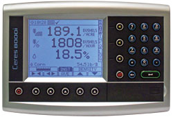
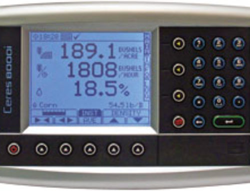
Console Mounting
Console mounting is typically personal preference. This combine has the RAM mount bracket installed on the right hand post. This is the most common location but any location in the cab will work. In the cab is also 12 volt switched power. Make sure a solid ground is used and route the power cable to the junction box. Follow the supplied wiring diagram for the correct PIN locations for each of the sensor wires.
If you have any questions in regards to installing the Loup 8000i Yield Monitor please email info@loupelectronics.com or call 1-877-489-5687.
